
Green Hydrogen and Energy Storage in 2025
- Mr_Solid.Liquid.Gas
- Aug 31, 2025
- 18 min read
Updated: Sep 8, 2025

Green Hydrogen, Energy Storage, and Low-Carbon Transport in 2025

This playbook brings together green hydrogen, long-duration energy storage (LDES), and the road-to-wheel powertrains that actually move people and goods.
It is written for readers who want practical, search-friendly clarity on how Solid Oxide Electrolysers (SOEs), hydrogen hubs, Underground Hydrogen Storage (UHS), and grid batteries fit alongside Internal-Combustion Engines (ICE), Hybrid Electric Vehicles (HEVs and Plug-in Hybrids, PHEVs), Battery-Electric Vehicles (BEVs), hydrogen engines (H2-ICE), and Fuel-Cell Electric Vehicles (FCEVs).
We define acronyms on first use and keep the narrative anchored in use-cases and system economics—so every section helps answer a real buying, planning, or investment question.
Why these topics together?
Because decarbonisation succeeds only when production, storage, and end-use connect. Green hydrogen is most compelling where heat and e-fuel synthesis align (SOE advantage) and where hubs cluster supply, storage, and offtake.
Storage is not one thing: batteries (seconds–hours), thermal and compressed-air (hours), hydrogen and pumped hydro (days–seasonal) each solve different problems. On roads, BEVs thrive where charging is easy; hybrids bridge gaps; RNG (biomethane) vehicles turn waste into fuel; H2-ICE and FCEVs target heavy duty and high-uptime routes. The common thread is matching duty cycles to the right technology at the lowest Levelised Cost of Storage (LCOS) or transport service.
Primary keywords: green hydrogen, solid oxide electrolyser, hydrogen hubs Europe, underground hydrogen storage, LFP vs solid-state batteries, grid storage, BEV vs hybrid vs hydrogen, biogas vehicles, H2 engine, fuel-cell vehicle, long-duration energy storage, seasonal storage. Secondary keywords: PEM electrolyser, alkaline electrolyser, RFNBO certification, salt cavern storage, V2G, SMR/AMR nuclear fission, nuclear fusion progress.
Reading map:
Part 1 covers hydrogen production and storage;
Part 2 spans powertrains (ICE, hybrids, BEVs, RNG, H2-ICE, FCEV, smart charging);
Part 3 places storage within fossil, renewable, and nuclear generation;
Part 4 closes with an evidence-first conclusion.
If you are here from search, jump straight to the section that matches your question and follow the cross-links—each sub-article stands alone, but the system view is where the value compounds.
1.1 Solid Oxide Electrolysers (SOE) Efficiency Leap — Why High Temperature Changes the Game

Green hydrogen is only as compelling as the efficiency and reliability of the machines that split water. Solid Oxide Electrolysers (SOEs) operate at high temperature—typically 700–850 °C—where electrochemical kinetics are fast and steam (H2O) is already part-way to becoming hydrogen (H2).
By contrast, Proton Exchange Membrane (PEM) and Alkaline (ALK) electrolysers run at low temperature; they are proven and scalable but must supply more electrical energy to drive the same reaction. The SOE proposition is simple: feed the system with heat—preferably waste heat from industry or low-carbon heat—and you can reduce the electrical demand per kilogram of hydrogen, lifting round-trip efficiency at the system boundary.
Inside an SOE, oxygen ions move through a dense ceramic electrolyte, commonly yttria-stabilised zirconia (YSZ). Nickel-based cermets act as fuel electrodes, and perovskite oxygen electrodes such as lanthanum strontium manganite/cobalt ferrite (LSM/LSCF) complete the stack. At temperature, ohmic losses drop and reaction rates increase, enabling electrical efficiencies in the mid-80s% (Higher Heating Value basis) when integrated well with steam generation and heat recovery.
Co-electrolysis—a headline SOE feature—simultaneously reduces H2O and carbon dioxide (CO2) to form syngas (CO + H2). That directly feeds e-methanol, e-kerosene, or other e-fuels, cutting out an extra reverse water-gas shift step and saving energy and plant complexity.
The practical questions are durability and cycling.
Thermal expansion mismatches, redox cycling on nickel, and contaminants from process gases challenge stack lifetime. Modern designs use graded electrodes, improved seals, robust interconnects, strict gas clean-up, and controlled start-stop protocols to protect the cell. Balance-of-plant (BoP) matters as much as stacks: you need reliable steam generation, heat exchangers, gas cleanup/drying, and power electronics that can follow variable renewable electricity without thermal shock.
Capital expenditure (CAPEX) falls with scale and standardisation; operating expenditure (OPEX) falls when waste heat is available.
When do SOEs beat PEM or ALK? Two conditions push them ahead on total cost of ownership (TCO): first, access to cheap, low-carbon heat at the right grade (200–500 °C for feed pre-heat and steam); second, a co-electrolysis value chain where syngas is the desired intermediate.
Examples include chemicals complexes, refineries migrating to e-fuels, and future net-zero steel routes where off-gases provide heat. In these cases, the “electrical-to-hydrogen” metric underestimates the real advantage; the correct lens is “energy-to-molecule” with smart heat integration.
Risks remain. High-temperature materials and seals are more complex than polymer stacks; start/stop penalties mean duty cycles should be planned; and bankability still trails PEM/ALK. But the direction of travel is clear: where heat is abundant and e-fuels are the output, SOEs can lift efficiency, trim plant count, and improve overall project economics.
As renewable energy surpluses grow and industrial sites decarbonise, expect hybrid campuses that use PEM for flexible ramping and SOE for steady, high-efficiency baseload—proving that the right tool depends on the job, not ideology.
1.2 Hydrogen Hubs in Europe (2025): Ports, Pipelines, and the Power of Clustering

A hydrogen “hub” is not just an electrolyser farm; it is a cluster that co-locates production, storage, transport, and offtake so molecules travel short, cheap, and safe paths.
In Europe, ports and industrial regions are natural hubs: offshore wind connects to onshore electrolyser yards; nearby steel, chemicals, and refineries buy hydrogen (H2) under long-term contracts; and shared pipelines move molecules between anchor users.
Clustering lowers unit costs through shared infrastructure, coordinated safety, and better capacity factors.
European jargon matters. Renewable Fuels of Non-Biological Origin (RFNBO) define whether H2 and e-fuels count as “renewable” under regulation. Liquid Organic Hydrogen Carriers (LOHC) let H2 hitch a ride on a liquid molecule for easier shipping and storage, while ammonia (NH3) and liquid hydrogen (LH2) are gaining ground as import/export vectors.
The “hydrogen backbone” concept—a trans-European high-pressure pipeline system repurposed from natural gas corridors—aims to knit hubs together so supply, demand, and storage can balance across borders.
Ports versus inland clusters is a trade-off. Ports bring import optionality (NH3/LH2), bunkering, and excellent grid connections. Inland hubs excel where very large offtakers (steel, fertiliser, district heat) sit next to salt caverns for underground storage. Both benefit from shared compression, drying, and metering skids, as well as coordinated safety cases and emergency response.
Certification frameworks ensure electrons feeding “renewable hydrogen” are additional, temporal, and geographical matches to production, increasing investor confidence but also adding operational constraints.
Why now? Offshore wind build-out, high CO2 prices, and energy-security priorities are aligning. Early hubs prioritise hard-to-abate industry, heavy mobility depots, and power-to-gas links that soak up surplus renewables and provide grid services.
Over time, hubs can add e-fuel synthesis (e-methanol, e-kerosene), carbon capture for negative-emissions fuels, and cross-border pipeline interties to smooth seasonal swings via cavern storage.
The pitfalls are real: permitting and public acceptance for new pipelines, harmonising safety codes across countries, and avoiding stranded assets if demand develops slower than hoped.
Bankable anchor loads are essential; credible governance and open-access rules prevent monopolies and encourage competition. Done well, hubs turn hydrogen from a point solution into a system tool—linking windy coasts to industrial heartlands and making Europe’s decarbonisation physically, not just politically, connected.
1.3 Seasonal Underground Hydrogen Storage (UHS): Caverns, Integrity, and the Winter Draw

Electricity is instant; heat demand is seasonal. To bridge summer renewable surpluses to winter needs, we need long-duration, large-scale storage. Underground Hydrogen Storage (UHS) uses geology as the tank.
Three options dominate: salt caverns solution-mined within thick halite formations; depleted gas fields repurposed for hydrogen (H2); and deep aquifers with appropriate seals. Salt caverns are the most mature: salt is self-healing, nearly impermeable, and compatible with high cycling rates.
A cavern is never fully empty. “Cushion gas” remains to maintain pressure and keep the cavern stable; working gas is the portion you can inject and withdraw seasonally. Typical surface kit includes multi-stage compressors, dryers to control dew point (H2 attracts moisture), metering, and safety valves.
Gas quality matters: oxygen traces, water, and sulphur compounds can embrittle steels and poison downstream fuel cells or turbines, so purification and material selection are central to the design.
Depleted fields unlock huge capacities but raise specific risks. Hydrogen is a tiny molecule; it can diffuse through seals and interacts differently with rocks and well cements than methane.
Microbial consumption is another consideration: subsurface microbes can metabolise H2, producing methane (CH4) or hydrogen sulphide (H2S) if left unchecked. Continuous monitoring—pressure/flow profiles, geophysical surveys, tracer tests—and well integrity programs mitigate these risks.
With the right geology and refurbishment, fields may offer strategic seasonal buffers measured in terawatt-hours.
Why seasonal at all? Power systems dominated by wind and solar see multi-week doldrums and low-sun winters.
Batteries excel from seconds to hours; pumped hydro can cover hours to days given geography. UHS targets weeks to months. It enables hybrid assets: electrolyser-to-cavern in summer, cavern-to-combined-cycle gas turbine (CCGT) or fuel cell in winter; or hydrogen to district heat via boilers and heat pumps. It also supports industrial reliability—ensuring steel or fertiliser plants don’t shutter in calm, cold spells.
Public acceptance and permitting are non-trivial: subsurface rights, monitoring obligations, and community benefit sharing must be clear. But the system value is high. With caverns beneath ports and industrial clusters, Europe can time-shift cheap summer electrons into winter molecules, reducing curtailment, stabilising energy bills, and adding resilience to the net-zero backbone.
1.4 Grid Storage Showdown: LFP vs Solid-State Batteries (SSB) for Stationary Use

Lithium Iron Phosphate (LFP) dominates utility-scale batteries because it is safe, inexpensive, and durable. Solid-State Batteries (SSB) promise non-flammable electrolytes and higher energy density by replacing liquid electrolyte with a solid.
But the priorities for grid storage differ from cars: footprint and gravimetric energy matter less; safety, cycle life, cost per delivered kilowatt-hour (kWh), and ease of integration matter more. The Levelised Cost of Storage (LCOS)—a function of CAPEX, OPEX, efficiency, degradation, and cycles per year—ultimately decides winners.
LFP containers offer 88–92% round-trip efficiency at the AC bus when paired with modern power conversion systems. They integrate well with solar plants for four-to-eight-hour shifts and provide ancillary services (frequency, ramping).
Fire risk is managed with segregation, off-gas detection, and suppression; codes and siting practices are now mature. By contrast, SSB remains pre-commercial for large, containerised formats. The solid electrolyte (sulphide, oxide, or polymer) can improve safety and high-temperature tolerance and, in theory, reduce thermal propagation risk—but manufacturing scale, interface resistance, stack pressure, and cost are still being solved.
Where might SSB fit? If developers can mass-produce large, stable cells with low impedance and long cycle life, SSB could reduce balance-of-system costs by simplifying thermal management and improving partial-state-of-charge durability.
For long duration (>8 h), however, alternative chemistries—sodium-ion for cost, or flow batteries that decouple power (stack size) from energy (tank size)—may compete more directly with LFP than SSB does. Remember that stationary containers can be larger and heavier; they don’t need the energy density premium that makes SSB attractive in vehicles.
Bankability matters. LFP has fleets of field data across climates and duty cycles; insurers, financiers, and fire marshals understand it. Early SSB projects will need performance guarantees, conservative warranties, and clear maintenance playbooks. Until then, expect the market to be pragmatic: LFP for most short-to-medium duration; sodium-ion emerging for cost-sensitive sites; flow batteries for 8–12 h; and hydrogen, thermal, or pumped hydro for multi-day to seasonal needs.
Stationary storage is a portfolio, not a duel—each asset earns its place by matching the duty cycle at the lowest LCOS.
2.1 Internal-Combustion Engines (ICE) 101: Cycles, Losses, and Cleaner Burn

An Internal-Combustion Engine (ICE) converts chemical energy to motion by compressing air-fuel mixtures and igniting them. The common thermodynamic cycles—Otto (spark-ignited petrol), Diesel (compression-ignition), and Atkinson/Miller (valve timing tricks to reduce pumping loss)—trade efficiency, torque curve, and emissions. Turbocharging and downsizing recover exhaust energy and improve specific power, but friction and heat losses still limit brake thermal efficiency in light-duty engines to ~35–42% under best conditions.
Modern ICEs are marvels of clean-up. Gasoline Direct Injection (GDI) improved efficiency but created fine particulates; gasoline particulate filters (GPF) now catch them. Diesel Particulate Filters (DPF) oxidise soot, while Selective Catalytic Reduction (SCR) uses urea to reduce nitrogen oxides (NOx) in diesel exhaust. The Three-Way Catalyst (TWC) in stoichiometric petrol engines simultaneously reduces NOx, oxidises CO, and burns unburnt hydrocarbons when the air-fuel ratio is tightly controlled. Exhaust Gas Recirculation (EGR) tempers combustion temperatures to further curb NOx.
Where do synthetic and bio-fuels fit? Drop-in, low-carbon liquids can decarbonise legacy fleets without new drivetrains, but supply is limited and costly. Engine calibration matters: fuel properties (octane/cetane, latent heat, laminar flame speed) inform injection timing, boost, and spark. Increasingly, ICEs sit inside hybrid powertrains so they can operate near efficient set points, with the battery handling transients and regenerative braking recapturing energy that friction brakes would waste.
The future role of ICE is narrowing to use-cases where high energy density, rapid refuelling, and extreme durability under high loads remain critical—heavy machines off-grid, remote regions, or as range extenders. For everyday urban mobility, the combination of emissions regulation, total cost of ownership, and maturing electric alternatives keeps pushing ICEs toward hybridisation or retirement. Engineering focus has shifted from raw peak efficiency to system-level optimisation within mixed fleets, where ICEs, motors, and batteries cooperate to move people and goods with fewer emissions per kilometre.
2.2 Hybrids Demystified: Series, Parallel, and Plug-In (PHEV) Architectures
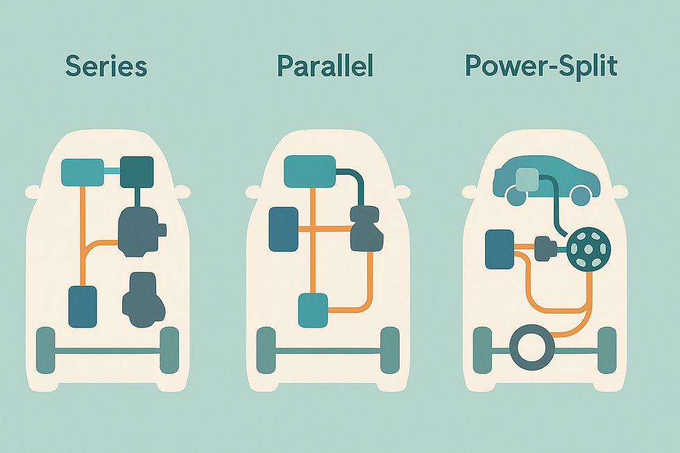
Hybrids are not a single technology but a family of architectures that combine an engine with one or more electric machines and a battery. A conventional Hybrid Electric Vehicle (HEV) charges its battery from the engine and from regenerative braking; a Plug-in Hybrid Electric Vehicle (PHEV) also charges from the grid to provide a pure-electric range. The control problem is deciding when the engine should run, at what load, and when the electric motor should propel or regenerate—all while keeping the battery within its State of Charge (SOC) window and the catalysts warm for emissions control.
Three archetypes dominate. Series hybrids route engine power only through a generator; the wheels are always driven by the electric motor. This is efficient in stop-start urban cycles where the engine can run near its sweet spot or switch off. Parallel hybrids couple the engine mechanically to the wheels via a clutch or a planetary gearset so both engine and motor can drive the axle.
Power-split systems blend these modes seamlessly, enabling electric launch, strong regenerative braking, and efficient cruising. PHEVs add a larger battery and onboard charger, shifting many short trips to electricity and turning the engine into a long-range extender.
Real-world results depend on calibration and use. Short commutes that charge daily play to PHEV strengths; long motorway drives with a depleted battery don’t. Cold starts raise emissions until aftertreatment heats up; hybrids use electric heating and thermal management to accelerate “light-off.”
The battery and inverter must handle bursts of power and frequent cycling; silicon-carbide (SiC) devices improve switching losses, and careful thermal design preserves lifetime. Tyres, mass, and aerodynamics still matter—a hybrid is only as efficient as the vehicle it sits within.
In policy terms, hybrids are a pragmatic bridge for markets where charging is scarce or electricity is carbon-intensive. They also shine in fleets that value uptime and familiar refuelling. But they are not a license to ignore charging behaviour or vehicle mass.
The winning hybrid is transparent to the driver, frugal in fuel, quiet in town, and honest about its performance on long trips. Done well, hybrids reduce fuel use and emissions today while building the supply chains—motors, inverters, batteries—that pure Battery Electric Vehicles (BEVs) scale tomorrow.
2.3 Battery-Electric Vehicles (BEVs): Motors, Inverters, Packs, and Charging Reality
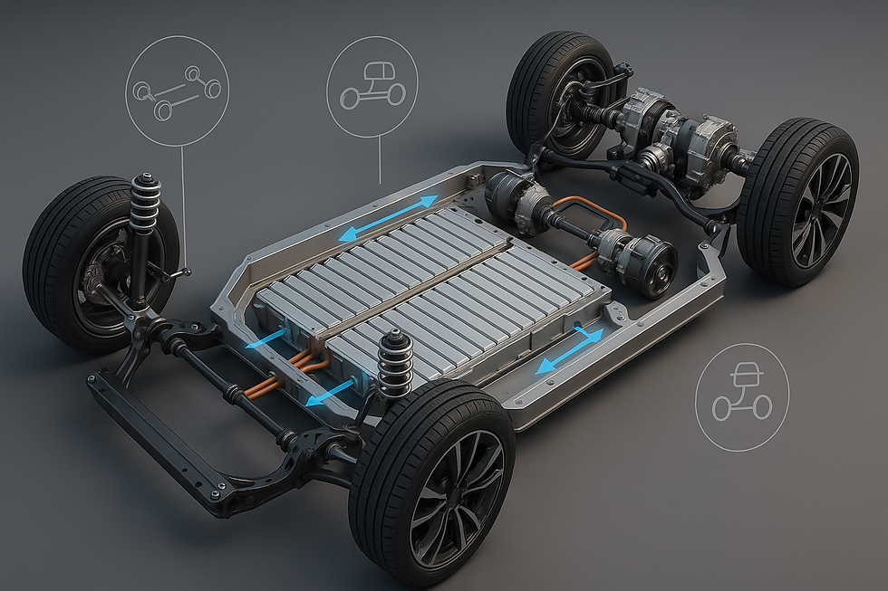
A Battery-Electric Vehicle (BEV) replaces the engine with an electric motor, inverter, and a large lithium-ion battery pack. Motor choice—permanent-magnet synchronous for efficiency and torque density, or induction for rare-earth independence—drives thermal and control design. The inverter turns DC battery power into AC motor currents; silicon-carbide (SiC) switches reduce losses and shrink cooling hardware. The Battery Management System (BMS) estimates State of Charge (SOC) and State of Health (SOH), balancing cells and protecting the pack from abuse.
Pack architecture is evolving from module-based to “cell-to-pack” or even structural packs integrated into the body. Thermal management is critical: cold batteries resist fast charging and hot batteries degrade faster, so liquid cooling and pre-conditioning are now standard. Fast-charge curves taper as cells approach high SOC to protect the electrodes; drivers see this as “the last 20% is slower,” a universal chemistry reality. Software is as important as hardware: routing, charger discovery, and plug-and-charge authentication knit the experience together.
Real-world efficiency is dominated by aerodynamics (drag rises with speed squared), mass (especially in hills and stop-go), tyres, and climate control. In cold climates, heat pumps and cabin pre-heat mitigate range loss. Grid carbon intensity sets the emissions profile of charging; as grids decarbonise, BEVs get cleaner in use. Battery lifecycle is managed through second-life storage applications and recycling of nickel, cobalt, lithium, copper, and aluminium—both to lower environmental impact and to hedge raw-material risk.
Infrastructure is uneven but improving. Urban kerbside, workplace, and rapid-charging corridors each solve a different need; depots orchestrate fleets to charge off-peak. Vehicle-to-grid (V2G) and vehicle-to-home (V2H) turn parked BEVs into flexible grid assets when standards and tariffs align.
The upshot is simple: when charged on low-carbon electricity and right-sized for the job, BEVs deliver quiet, efficient transport with minimal local air pollution—and they drag the rest of the power sector forward by incentivising cleaner power.
2.4 Biogas and Renewable Methane Vehicles: From Digesters to Depots

Biogas starts with biology: anaerobic digesters convert organic waste into a mixture of methane (CH4) and carbon dioxide (CO2). Upgrading removes CO2, hydrogen sulphide (H2S), and water to yield biomethane—also called Renewable Natural Gas (RNG). Vehicles then use RNG as Compressed Natural Gas (CNG) or Liquefied Natural Gas (LNG). The appeal is circularity: waste streams become fuel, local air quality improves versus diesel, and lifecycle emissions drop sharply when methane leakage is controlled across the chain.
Spark-ignited natural-gas engines are mature for buses and trucks; dual-fuel systems can blend small diesel pilot injections for ignition with methane as the primary energy. Methane slip—the emission of unburned CH4—must be minimised because methane is a potent greenhouse gas. Three-way catalysts on stoichiometric engines, oxidation catalysts on lean-burn engines, and tight calibration keep slip low. Fuel quality is crucial: siloxanes from wastes can form abrasive deposits, so upgrading and filtration protect engines and aftertreatment.
Infrastructure can be modular. On farms, small-scale upgrading plus a CNG dispenser may fuel tractors and local fleets; in cities, large depots receive pipeline-injected RNG certificated by origin. Grid injection allows RNG to displace fossil gas beyond transport, but dedicated transport use often maximises CO2 benefit where diesel displacement is highest. Economics hinge on waste gate fees, renewable credits, and stable demand from captive fleets such as refuse trucks and city buses that return to base daily.
RNG is not limitless; sustainable feedstock caps supply. But within those limits, biogas vehicles deliver dependable decarbonisation today with familiar drivetrains, fast refuelling, and proven reliability. They complement electrification in routes where duty cycles, topography, or harsh weather complicate batteries—and they turn a methane liability into an asset.
2.5 Hydrogen Internal-Combustion Engines (H2-ICE): Fast Flames, Clean Carbon, and NOx Control

A Hydrogen Internal-Combustion Engine (H2-ICE) burns hydrogen (H2) in cylinders much like a gasoline engine burns petrol. The advantages are compelling: no CO2 from the cylinder, fast flame speed for brisk combustion, and familiar engine manufacturing. The challenges are different: pre-ignition and backfire risks due to low ignition energy, high flame speed that can cause knock-like pressure rise, and nitrogen oxides (NOx) formed at high combustion temperatures.
Two injection strategies dominate. Port Fuel Injection (PFI) introduces H2 upstream of the intake valve; it is simple but displaces some intake air and raises backfire risk. Direct Injection (DI) sprays H2 late in the compression stroke, enabling lean, knock-resistant operation with higher power density. Exhaust Gas Recirculation (EGR), cooled charge air, and careful spark control suppress NOx by keeping peak temperatures in check. Aftertreatment closes the loop: lean NOx traps or SCR systems remove residual NOx, while three-way catalysts become viable under near-stoichiometric calibration with DI.
Onboard storage dictates range and packaging. Heavy trucks often use 350-bar composite cylinders for depot refuelling; light vehicles favour 700-bar to save space. Refuelling hardware precools H2 to avoid overheating tanks during fast fills. Compared with Fuel-Cell Electric Vehicles (FCEVs), H2-ICEs are less efficient but cheaper to build and more tolerant of fuel impurities. They suit high-load, long-haul applications and retrofits where existing engine plants and supply chains can be leveraged quickly.
Where do H2-ICEs make sense system-wide? In corridors with 350-bar truck refuelling, at ports and industrial hubs where green H2 is abundant, and as transitional technology while fuel-cell costs fall.
Policy should reward actual emissions outcomes, including NOx and upstream hydrogen carbon intensity, rather than drivetrain ideology. Done properly, H2-ICEs offer a pragmatic route to deep decarbonisation in heavy duty without waiting for perfection.
2.6 Fuel-Cell Electric Vehicles (FCEVs): From PEM Stack to Driven Wheels

A Fuel-Cell Electric Vehicle (FCEV) converts hydrogen (H2) into electricity in a Proton Exchange Membrane Fuel Cell (PEMFC), producing water and heat as by-products. The stack consists of membrane-electrode assemblies sandwiched between bipolar plates; hydrogen flows on the anode, oxygen from air on the cathode. Platinum-group catalysts accelerate the reactions, while humidification and temperature control maintain performance and durability. Freeze-start capability—reliable operation after sub-zero soaks—is a key benchmark for road vehicles.
The fuel-cell rarely works alone. A buffer battery absorbs regenerative braking and supplies bursts of power for acceleration; a DC/DC converter ties the stack and battery to the traction bus; the inverter feeds an electric motor. This hybridisation lets the stack run near its efficiency sweet spot, extending life. Balance-of-plant (BoP)—air compressor/expander, humidifier, coolant loops, hydrogen recirculation ejector or blower—consumes part of the generated power and must be compact, quiet, and reliable.
Infrastructure is the chicken-and-egg. Stations compress, chill, and dispense H2 at 700 bar for cars and 350 bar for heavy trucks; pre-cooling prevents tank over-temperature during fast fills. Supply chains matter: the carbon intensity of hydrogen (from electrolysis powered by renewables, or from natural gas with carbon capture) determines well-to-wheel emissions. Safety engineering—leak detection, venting, crash protection—is mature but must be executed flawlessly to win public trust.
Where do FCEVs fit? High-utilisation fleets (taxis, delivery vans, buses), long-haul trucks with tight duty cycles, and regions where grid constraints or downtime make battery charging impractical. As stack costs fall and durability improves, FCEVs can sit alongside BEVs in a complementary split: electrons where charging is easy, molecules where energy density, uptime, and refuelling speed are paramount.
The drivetrain is electric in both cases—the only difference is how you carry the energy.
2.7 Lifecycle and Infrastructure: The Real-World Ledger for ICE, Hybrids, BEVs, RNG, and H2

Decarbonising transport is an accounting problem as much as an engineering one. Lifecycle Assessment (LCA) tallies emissions from cradle-to-grave: mining, manufacturing, use, and end-of-life. Well-to-Wheel (WTW) or Well-to-Wake for shipping narrows the lens to fuel production and use. The answers depend on local grids, duty cycles, and how vehicles are charged or fuelled in practice—not brochure numbers. That is why policy and investment should reward measured outcomes per kilometre or tonne-kilometre.
Internal-Combustion Engines (ICE) fed with fossil fuels have high use-phase emissions; hybrids reduce them by operating engines efficiently and recapturing braking energy. Battery-Electric Vehicles (BEVs) shift emissions to the power sector: if the grid is clean, use-phase drops dramatically; if not, gains are muted until the grid decarbonises. Renewable Natural Gas (RNG) vehicles can achieve deep reductions when methane leakage is controlled, sometimes even net-negative if they prevent fugitive emissions from waste. Hydrogen pathways vary widely: green hydrogen from renewable electrolysis is low-carbon, while hydrogen from natural gas without capture is not.
Infrastructure is the second ledger. Chargers must be reliable, ubiquitous, and powered by low-carbon electricity; depots need orchestrated, tariff-aware charging. Hydrogen stations must deliver certified, low-carbon H2 at the right pressure with minimal downtime. RNG supply chains require leak-tight collection, upgrading, and dispensing. Recycling and second-life uses reduce the manufacturing footprint of batteries and fuel-cell stacks by recovering critical materials like lithium, nickel, cobalt, and platinum group metals.
No single drivetrain wins everywhere. Urban light-duty is trending BEV; sparse regions and heavy duty may split between RNG, hydrogen fuel-cell, and hydrogen ICE depending on corridors and depots. The best fleets run pilots, measure real energy and maintenance, and then scale what works. Success is a mixed ecosystem governed by evidence: lowest cost per avoided tonne of CO2e while meeting service levels and air-quality goals.
2.8 Smart Charging, Demand Response, and Vehicle-to-Grid (V2G)
Charging strategy can make or break the economics of electrified fleets. Smart charging shifts electricity consumption to cheaper, cleaner hours using tariffs and grid signals—a form of Demand Response (DR). Depot software staggers starts, caps peaks, and preconditions vehicles just in time for routes. At the household scale, time-of-use tariffs and automated schedules cut bills while reducing stress on transformers and feeders.
Vehicle-to-Grid (V2G) and Vehicle-to-Home (V2H) go further by exporting power back to the grid or the building. Bidirectional chargers and inverters enable parked vehicles to provide frequency response, peak shaving, or backup power. The hurdles are standardisation, battery warranty concerns, and the need for aggregators that can coordinate thousands of vehicles reliably. In practice, early wins are in depots and campuses where duty cycles are predictable, telematics are standard, and the operator captures both energy and resilience value.
Data is the hidden enabler. Telematics inform right-sizing of packs, charger locations, and spare energy available for V2G. Weather and renewable forecasts drive charging plans. Integration with building management systems couples EVs to heat pumps, solar PV, and batteries, turning sites into microgrids that can island during outages. Cybersecurity and privacy must be designed in from the start; connected powertrains are critical infrastructure by another name.
As grids absorb more wind and solar, flexibility is worth real money. Smart charging and V2G transform EVs from passive loads into active assets—accelerating renewable adoption, cutting system costs, and improving reliability. The drivetrain revolution becomes a grid revolution, too.
3.1 Energy Storage in Context: Fossil, Renewables, Fission, and Fusion

Storage solves a timing mismatch: we generate energy when nature allows and consume it when people need it. Fossil plants—especially Combined-Cycle Gas Turbines (CCGT)—are dispatchable, mature, and compact. Their advantages are flexibility and high capacity factor; their disadvantages are carbon dioxide (CO2) and exposure to fuel prices and carbon policies. Renewables—wind, solar, hydro, geothermal—are clean in operation and rapidly deployable, but wind and solar are variable and require transmission and land.
Nuclear fission provides steady, low-carbon baseload with very high capacity factor. Large reactors and Small Modular Reactors (SMRs) can both load-follow to a degree and couple well with electrolysers and district heating, soaking up off-peak generation to make hydrogen (H2) or hot water. Nuclear fusion remains research: its potential is vast—abundant fuel and inherent safety—but materials science and sustained net-power operation are still under development.
Match storage to need.
Short-duration storage (seconds to hours) includes batteries and flywheels for frequency and ramping. Medium duration (4–12 h) uses larger battery blocks, thermal stores like molten salt, or compressed-air. Long Duration Energy Storage (LDES)—days to seasons—leans on pumped-hydro reservoirs, hydrogen linked to turbines or fuel cells, underground thermal stores, or redox flow batteries that decouple power from energy. The Levelised Cost of Storage (LCOS) is meaningful only when tied to a duty cycle and a siting context; urban fire codes, land availability, water, and noise constraints all shape the answer.
The portfolio view is the only honest one. Use fission and firmed renewables to anchor supply; add short-duration storage to stabilise; stack medium duration to crush evening peaks; and deploy seasonal buffers such as Underground Hydrogen Storage (UHS) to ride out calm, cold winters. The result is a system that is cleaner and more resilient than any single technology could deliver. Storage is not a silver bullet—it is the magazine that lets the energy system fire reliably, whatever the weather.
4.1 Conclusion: A Portfolio, Not a Posture

Across production, storage, and wheels, the decarbonisation story is increasingly pragmatic. Solid Oxide Electrolysers (SOEs) thrive where heat and e-fuel synthesis align; Proton Exchange Membrane (PEM) and Alkaline (ALK) electrolysers offer flexible ramping.
Hydrogen hubs crystallise around ports and industrial clusters, tying offshore wind, caverns, and offtakers into bankable systems. Seasonal Underground Hydrogen Storage (UHS) is not a luxury but a necessity in high-renewables countries with winter demand peaks. On the grid, Lithium Iron Phosphate (LFP) delivers today’s batteries; Solid-State Batteries (SSB), sodium-ion, and flow systems extend options rather than replace them outright.
On the road, Internal-Combustion Engines (ICE) give way to hybrids and Battery-Electric Vehicles (BEVs) where charging is easy; Renewable Natural Gas (RNG) and hydrogen engines or Fuel-Cell Electric Vehicles (FCEVs) take heavy duty and corridor work. Smart charging and Vehicle-to-Grid (V2G) flip vehicles into flexible grid assets. The through-line is systems thinking: match technology to duty cycle, site, and supply chain; measure lifecycle emissions honestly; and iterate fast with data from pilots.
There is no virtue in purity tests. The winning projects mix molecules and electrons, new builds and retrofits, centralised and distributed assets. They bank the near-certain and pilot the promising. And they remember that efficiency is not just about thermodynamics but also about capital allocation—putting scarce euros, hours, and materials where they avoid the most carbon per unit of service. That is how the 2025 playbook turns into durable progress by 2030 and beyond.


We are offering you a variety of pedicure treatments like kids massage; best places for couple massages for your beautiful feet Aira Spa and wellness center are providing you a different type of services like Massage Airdrie Spa Airdrie, is the best registered massage therapy near me. and also help them stay healthy all year long. We use the best beauty product for our customer's glowing skin. Acupuncture Airdrie uses super-efficient nail salon in Airdrie mediceutical products to perform Threading Waxing in Airdrie, pedicure with its proven healing properties, and its intense relaxation qualities, Eyebrow Microblading in Airdrie, this fabulous range of products have been formulated with specific podiatry needs in mind. We also provide spa packages to your comp…